This is an old revision of the document!
Table of Contents
Quality of Service in IP Networks: An Experimental Approach
The global outcomes of this project consist of the following:
- Analyze the constraints of applications such as video transmission
- Analyze the impact of traffic shaping
- Deploy a DiffServ architecture and tune the configuration parameters
- Analyze the impact of QoS mechanisms in congestion scenarios
The description of the project and the tasks is available for download on Moodle.
-. Hardware
-. Software
The following tools can help in assessing the QoS on the platform:
- Install and compile netperf:
wget https://github.com/HewlettPackard/netperf/archive/master.zip
unzip master .zip
cd netperf-master/
./configure --enable-demo=yes
make
make install
- Install matplotlib and fping
apt-get install fping
apt-get install python-qt4
pip install matplotlib
Install flent
pip install flent
- Install VLC as in this tutorial.
-. Addressing
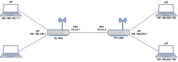
The addressing plan of the platform is shown in Fig. 3. Both routers have static addresses on their wan and lan interfaces. DHCP is activated on the LAN interfaces and static leases are configured so as to obtain the addresses on the terminals according to the figure.
-. Access and Configuration
SSH is activated on the two Raspberry Pi devices connected to the TP-LINK router. Thus, they can be accesses by typing ssh -l pi ip_address on any terminal. The default password is raspberry and the pi user is a sudoer. For advanced debugging, an HDMI cable is available so you can connect the Pi to a display monitor.
For both routers, SSH is also activated, and they can be accessed by any SSH client on the platform. For easiness, you can also connect to the WiFi interfaces (OpenWrt and GL-iNet SSID) and configure the routers form your personal laptop. The root password for GL-iNet is helloworld, while no password is set for OpenWrt.
Before you leave, make sure to go through the following steps.
- Gracefully shutdown the raspberry pi modules with
shutdown -h now. - Switch off the TP-LINK and remove the USB power cable from the GL-iNet.
- Power off the laptop.
-. [CO1] Connecting the Platform
Describe and analyze the basic steps for ensuring the platform connectivity: addressing and routing
- Accomplished
- Enable end-to-end communication
- Analyse the addressing and routing (routing tables, DHCP, etc.)
- Exceeded
- Identify the necessary commands and configurations for enabling end-to-end communication
In order to analyse the addressing and routing on the platform, we need to look carefully on the interface configuration and routing tables of the different devices.
Let us start with the routing devices. The routing table of the GL-iNet is shown using the command ip route and gives the following:
10.0.0.0/24 dev eth0  proto kernel  scope link  src 10.0.0.1 # loopback address
192.168.8.0/24 dev wlan0  proto kernel  scope link  src 192.168.8.1 # connection to the wifi interface
192.168.100.0/24 dev eth1  proto kernel  scope link  src 192.168.100.1 # connection to the LAN 192.168.100.0/24
192.168.200.0/24 via 10.0.0.2 dev eth0  proto static # static route to the 192.168.200.0/24 network via the interface
10.0.0.2 of the TP-LINK router
Similarly, the routing table of the TP-LINK router shows the following:
10.0.0.0/24 dev eth1  src 10.0.0.2 # connection to directly connected network 10.0.0.0/24
192.168.100.0/24 via 10.0.0.1 dev eth1 # static route to the network 192.168.100.0/24 via the interface
10.0.0.1 of the GL-iNet router
192.168.200.0/24 dev br-lan  src 192.168.200.1 # connection to our LAN 192.168.200.0/24
We note on the two routers that static routes are used in order to give access to the two LANs. Particularly, the configuration of the routers is given in the /etc/config/network files as on a typical OpenWrt system.
As given below, the configuration of the TP-Link router shows the static addressing of the interface eth0 (LAN interface) and the interface eth1 (WAN interface). We also note the section route that configures a static routers towards the LAN connected to the TP-LINK router.
- /etc/config/network
#Configuration of LAN interface:
config interface 'lan'
        option type 'bridge'
        option ifname 'eth0'
        option proto 'static'
        option ipaddr '192.168.200.1'
        option netmask '255.255.255.0'
        option ip6assign '60'

#Configuration of WAN interface:
config interface 'wan'
        option ifname 'eth1'
#       option proto 'dhcp'
        option proto 'static'
        option ipaddr '10.0.0.2'
        option netmask '255.255.255.0'

#Configuration of the static route :

config route
        option interface 'wan'
        option target '192.168.100.0'
        option netmask '255.255.255.0'
        option gateway '10.0.0.1'
Similarly, the configuration of the GL-iNET router below shows the following:
- The WiFi interface is configured with a static IP address 192.168.8.1/24
- The WAN interface is configured with a static IP address 10.0.0.1/24
- A static route enables GL-iNET to reach the network 192.168.200.0/24 via 10.0.0.2 of the other router.
- /etc/config/network
config interface 'lan'
        option force_link '1'
        option proto 'static'
        option ipaddr '192.168.8.1'
        option netmask '255.255.255.0'
        option ip6assign '60'
        option _orig_ifname 'eth1'
        option _orig_bridge 'false'

config interface 'wan'
        option ifname 'eth0'
        option hostname 'GL-iNet-b2d'
        option proto 'static'
        option ipaddr '10.0.0.1'
        option netmask '255.255.255.0'

config route
        option interface 'wan'
        option target '192.168.200.0'
        option netmask '255.255.255.0'
        option gateway '10.0.0.2'
The two routers allocate IP addresses using DHCP. In order to facilitate the usage of the platform, fixed allocations are configured for the end hosts. This is configured in /etc/config/dhcp on each router as in the following.
config dhcp 'lan'
        option interface 'lan'
        option start '100'
        option limit '150'
        option leasetime '12h'
        option dhcpv6 'server'
        option ra 'server'

config host
        option name 'pi2'
        option mac 'b8:27:eb:0f:f8:95'
        option ip '192.168.200.192'

config host
        option name 'pi3'
        option mac 'b8:27:eb:20:aa:54'
        option ip '192.168.200.193'
Finally, we verify the routing and addressing on the Raspberry Pi devices using ifconfig (or ip addr show) and ip route commands.
pi@raspberrypi:~ $ ifconfig
eth0      Link encap:Ethernet  HWaddr b8:27:eb:0f:f8:95
          inet addr:192.168.200.192  Bcast:192.168.200.255  Mask:255.255.255.0
          inet6 addr: fdd5:bc83:a776:0:2377:1496:eb81:1433/64 Scope:Global
          inet6 addr: fe80::20ae:134e:ae88:4bc5/64 Scope:Link
          inet6 addr: fdd5:bc83:a776::192/128 Scope:Global
          UP BROADCAST RUNNING MULTICAST  MTU:1500  Metric:1
          RX packets:1216 errors:0 dropped:3 overruns:0 frame:0
          TX packets:983 errors:0 dropped:0 overruns:0 carrier:0
          collisions:0 txqueuelen:1000
          RX bytes:229130 (223.7 KiB)  TX bytes:121127 (118.2 KiB)
pi@raspberrypi:~ $ ip route
default via 192.168.200.1 dev eth0  metric 202
192.168.200.0/24 dev eth0  proto kernel  scope link  src 192.168.200.192  metric                                                                                                                                                              202
-. iperf tool
Let us start with the application iperf. In the following, we present a short tutorial on the main functions of the perf tool.
- To launch iperf3:
- On the server side:
iperf3 -s - On the client side:
iperf3 -c 192.168.200.192, where 192.168.200.192is the IP address of the server.
- By default, the trafic sent by iperf uses TCP. In order to send UDP trafic with a specific bandwidth:
- On the client side: iperf3 -c 192.168.200.192 -u -b 2M
Here we set the bandwidth with UDP to 2Mbit/s. Note that by default, UDP sets the bandwidth to 1Mbit/s.
- To extend the transmission time(second) as well as the number packets sent:
- On the Client side:
iperf3 -c 192.168.200.192 -t 15
Note that by default, iperf3 sets the time to 10 seconds.
- To use reverse mode (server sends the trafic and client receives):
- On the Client side:
iper3 -c 192.168.200.192 -R
- To send multiple flows:
- On the Client side:
iper3 -c 192.168.200.192 -P 2 -t 60
Here we are sending two flows for one minute (60 seconds). We note that the average rate for the two flows can be different. However, this is not a fairness issue: we only need to extend the transmit time in order to have similar throughput for the two flows.
-. Flent Tool
Let us now analyze Flent application. Flent is a network benchmarking tools which allows to easily run network tests.
- On the Server side:
netserver & - To sent one TCP stream from the client to the server:
- On the Client side:
flent tcp_upload -p totals -l 60 -H 192.168.200.192 -t title2 -o test2.png
- To send 12 TCP streams:
- On the Client side:
flent tcp_12up -p totals -l 60 -H 192.168.200.192 -t title3 -o test3.png
-.VLC Tool
Let us now analyze the VLC application. VLC media player is a a highly portable multimedia player for various audio, video, streaming protocol.
- On the Server side: we open VLC media player : Go to media - stream - we add the desired video - Stream - Next - for the new destination we choose UDP legacy then we click on add - we add the destination IP address 192.168.100.111 (client) and the port number 1234 - next - we uncheck the active transcoding - next stream.
- On the client side: we open VLC and then we click on play, go to network and specify the network url:
udp:\\@:1234and finally we click on play.
-. [CO3] Shaping the Traffic
We first tried to limit the bandwidth using the following command cbq but it didn't work since cbq is not installed on the HP-PC:
tc qdisc add dev eth1 root handle 1: cbq avpkt 1000 bandwidth 8mbit
On the Wan interface eth0 of the router GL-iNet, the following command is used in order to limit the bandwidth of the outgoing traffic:
tc qdisc add dev eth0 root tbf rate 8000kbit burst 10kb latency 50ms
To verify the result of the configuration we used :
tc qdisc ls
After streaming VLC traffic and iperf UDP traffic with 6mbps to visualize the impact of the used command we noticed that the offered bandwidth is still the same 100 Mbps, therefore the same configuration should be done on the router TP-Link :
tc qdisc add dev eth1 root tbf rate 8000kbit burst 10kb latency 50ms
Now the link between the two routers has a bandwidth of 8 Mbps for both the incoming and outgoing traffic on them. In order to visualize the impact on the VLC video streamed from pi3 we generated UDP traffic from pi2 with 6mbps. The VLC video is affected giving that images of the video are pixelized.
If we want to apply this feature in one direction we have to remove the limitation of the bandwidth on one of the routers(in our case we applied it on GL-iNet router):
tc qdisc del dev eth0 root
Exceeded :
We run flent with VLC and we noticed that the video wasn't affected because flent uses TCP.
-. [PO2] Implementing QoS
The QoS will be implemented on the outgoing interface (Wan) of the router TP-Link. First, we have to check the existing configuration, on the router by typing the following command :
tc qdisc ls
To delete the previous configurations we can use :
tc qdisc del dev eth1 root
Traffic classification and scheduling : The scheduler we will be using is the Hierarchical fair-service curve (HFSC). We start by creating a common class for all types of traffic. The used commands for this are:
tc qdisc add dev eth1 root handle 1: hfsc default 20
tc class add dev eth1 parent 1: classid 1:1 hfsc sc rate 8000kbit ul rate 8000kbit
Supposing we have two types of traffic: Video UDP associated with class 1:40 running on destination port 1234, and iperf UDP with class 1:50 running on destination port 5201. In the first case, the dedicated bandwidth is ((87/100)*8000)= 6960 Kbit and in the second case it's 1040 Kbit. The following commands are used:
tc class add dev eth1 parent 1:1 classid 1:40 hfsc ls rate 6960kbit ul rate 8000kbit
tc class add dev eth1 parent 1:1 classid 1:50 hfsc ls rate 1040kbit ul rate 8000kbit
iptables -t mangle -A POSTROUTING -o eth1 -p udp --dport 1234 -j CLASSIFY --set-class 1:40
iptables -t mangle -A POSTROUTING -o eth1 -p udp --dport 5201 -j CLASSIFY --set-class 1:50
To see the iptables commands excecuted on the router we can use:
iptables -t mangle -L
-. [PO3] Analyzing QoS
In this section, we have to consider different congestion scenarios: The link between the two routers will have a bandwidth of 16 Mb/s, 8 Mb/s and 5 Mb/s.For each case, we will be considering both the implementation and the absence of QoS.
1. 16Mb/s
- Without QoS:
We have to create two different classes with exactly the same bandwidth allocated for each as if no QoS is applied. The following commands are used:
tc class add dev eth1 parent 1:1 classid 1:10 hfsc ls rate 16000kbit ul rate 16000kbit
tc class add dev eth1 parent 1:1 classid 1:20 hfsc ls rate 16000kbit ul rate 16000kbit
iptables -t mangle -A POSTROUTING -o eth1 -p udp --dport 1234 -j CLASSIFY --set-class 1:10
iptables -t mangle -A POSTROUTING -o eth1 -p udp --dport 5201 -j CLASSIFY --set-class 1:10
iptables -t mangle -A POSTROUTING -o eth1 -p tcp --dport 5202 -j CLASSIFY --set-class 1:20
- With QoS: First, we have to create a common class 1:1 for all types of traffic, as before. Then, the following commands are executed in order to create two classes: 1:20 for video udp traffic with a bandwidth of ((87*16000)/100) and 1:30 for iperf tcp and udp traffic with a bandwidth of ((13*16000)/100).
tc class add dev eth1 parent 1:1 classid 1:20 hfsc ls rate 13920kbit ul rate 16000kbit
tc class add dev eth1 parent 1:1 classid 1:30 hfsc ls rate 2080kbit ul rate 16000kbit
iptables -t mangle -A POSTROUTING -o eth1 -p udp --dport 1234 -j CLASSIFY --set-class 1:20
iptables -t mangle -A POSTROUTING -o eth1 -p udp --dport 5201 -j CLASSIFY --set-class 1:30
iptables -t mangle -A POSTROUTING -o eth1 -p tcp --dport 5202 -j CLASSIFY --set-class 1:30
We will be running three types of traffic:
- VLC video udp
- iperf udp traffic on destination port 5201
On the client side:
iperf3 -c 192.168.100.111 -u -b 50M -P 3 -t 80 -p 5201
- iperf tcp traffic on destination port 5202, using the following commands:
On the server side:
iperf3 -s -p 5202
On the client side:
iperf3 -c 192.168.100.111 -P 3 -p 5202 -t 75
The same commands found above are applied when configuring the link with a bandwidth of 4Mb/s and 8Mb/s.