This is an old revision of the document!
Table of Contents
Study of the LoRaWAN Downlink
IoT is mostly dominated by the uplink since the typical scenarios consist of sending measurement data from end-devices towards the network. However, in order to take full benefit from the integration of the Internet in the end-devices (this is one basic definition of IoT), downlink can not be neglected. For instance, the network can help in making decisions using the collected data. Then, decisions should to be sent back to the end-devices in order to be implemented: this is where the downlink comes into play.
-. Receive Windows in LoRaWAN
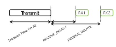
According to the LoRaWAN specification , each uplink transmission by an end-device of class A is followed by two short downlink receive windows as in Figure 1.
- The first receive window is implemented on the same channel and data rate as the uplink
- The second receive window is implemented on a predefined channel and data rate. This window can also be modified by MAC commands.
-. LoRaWAN End-to-end Platform
In order to study the downlink in LoRaWAN, we use the platform introduced in Deploying an End-to-End LoRaWAN Platform and ESIB IoT Challenge. This platform shown in Figure 2 represents a typical end-to-end communication chain and includes the following elements:
- Devices that communicate to one or more gateways via a wireless interface using single hop LoRa and implementing the LoRaWAN protocol. These devices are physically connected to sensors that generate data.
- Gateways or base stations that forward frames between the devices and the network server. Gateways are connected to the network server via IP interfaces.
- A LoRAWAN backend that implements the network server functions and provides frame control and security.
- Applications that enable to visualize and store the sensor data obtained from the devices.
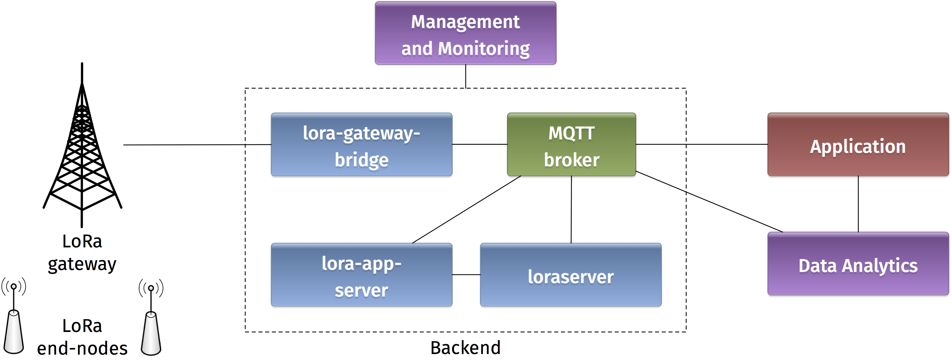
The backend installed in the platform is based on an open-source LoRaWAN network-server https://www.loraserver.io.
-. Sending Downlink Messages with MQTT
MQTT is a machine-to-machine (M2M)/“Internet of Things” connectivity protocol. It was designed as an extremely lightweight publish/subscribe messaging transport. The MQTT broker plays an important role in the loraserver backend. It enables to exchange messages between the software components of the backend (gateway bridge, application server, and network server) and also with the application. Therefore, uplink and downlink LoRaWAN messages transit via the MQTT broker.
-. Using mqtt-spy
mqtt-spy is an open source utility intended to help you with monitoring activity on MQTT topics. It has been designed to deal with high volumes of messages, as well as occasional publications. mqtt-spy is a JavaFX application, so it should work on any operating system with an appropriate version of Java 8 installed. A very useful tutorial is available on https://github.com/eclipse/paho.mqtt-spy/wiki.
You can use mqtt-spy to debug the messages received from the LoRaWAN devices. Start by configuring a new connection to the MQTT broker by simply adding the IP address of the broker in the Server URI field. Now you can subscribe to any MQTT topic. If you want to receive all messages arriving at the backend, you can use the generic topic #. You can also limit to the topic including the messages of any specific device: application/APPLICATION_ID/node/DEVICE_EUI/rx. The APPLICATION_ID and DEVICE_EUI are those used in the configuration of your LoRaWAN application server as explained in ESIB IoT Challenge.
In order to send downlink data to a specific device, you should publish the encoded message in the corresponding topic application/APPLICATION_ID/node/DEVICE_EUI/tx as follows:
{
    "reference": "abcd1234",                  // reference which will be used on ack or error (this can be a random string)
    "confirmed": false,                        // whether the payload must be sent as confirmed data down or not
    "fPort": 10,                              // FPort to use (must be > 0)
    "data": "...."                            // base64 encoded data (plaintext, will be encrypted by LoRa Server)
}
The payload sent by the MQTT client must be encoded in Base64.
-. Using IoT MQTT Dashboard
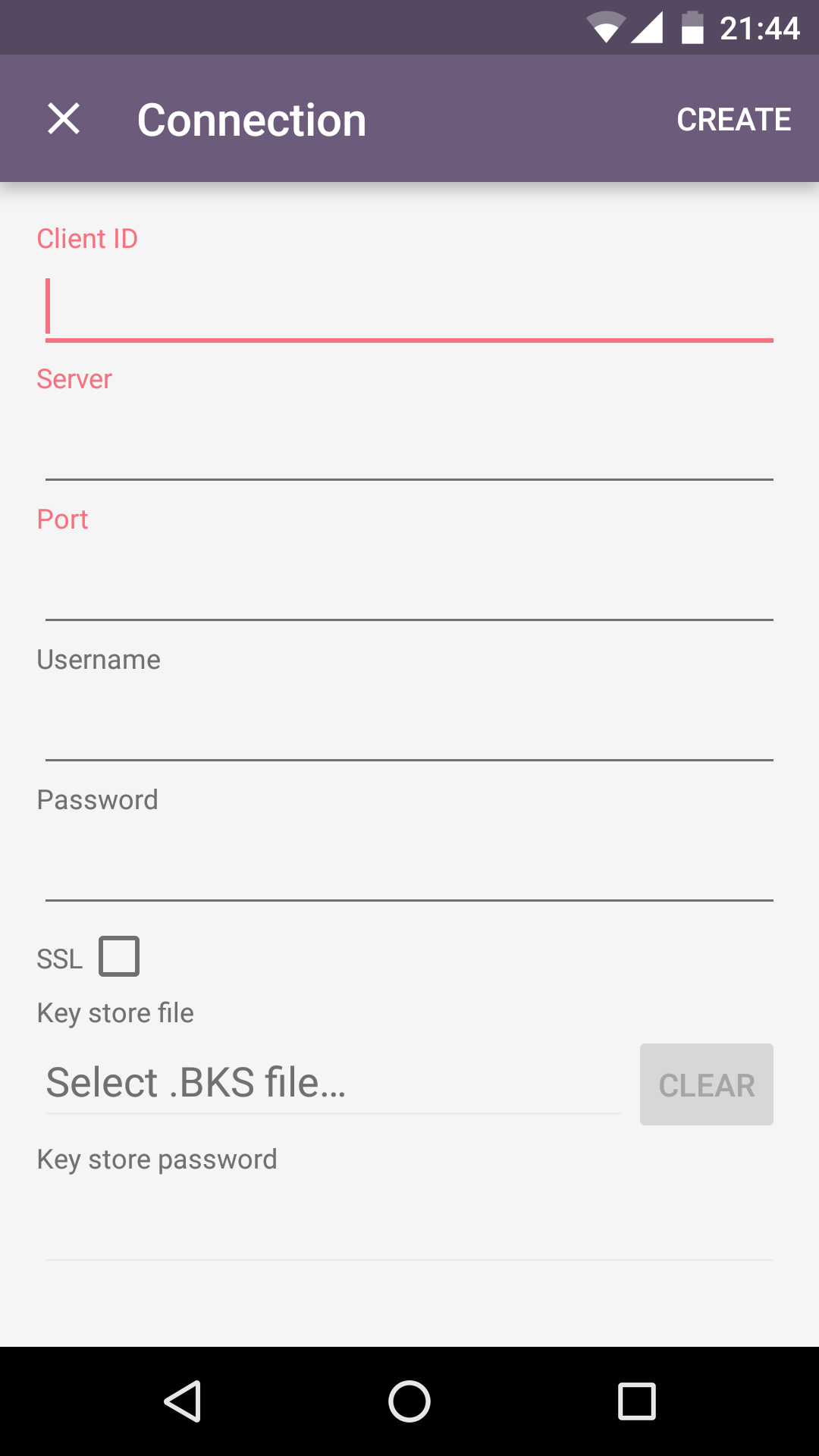
IoT MQTT Dashboard is a smartphone application available on Android platforms that enables to manage IoT projects using MQTT protocol. The availability on handheld devices makes this application attractive for situations where mobility is required, for instance in showrooms or road testing.
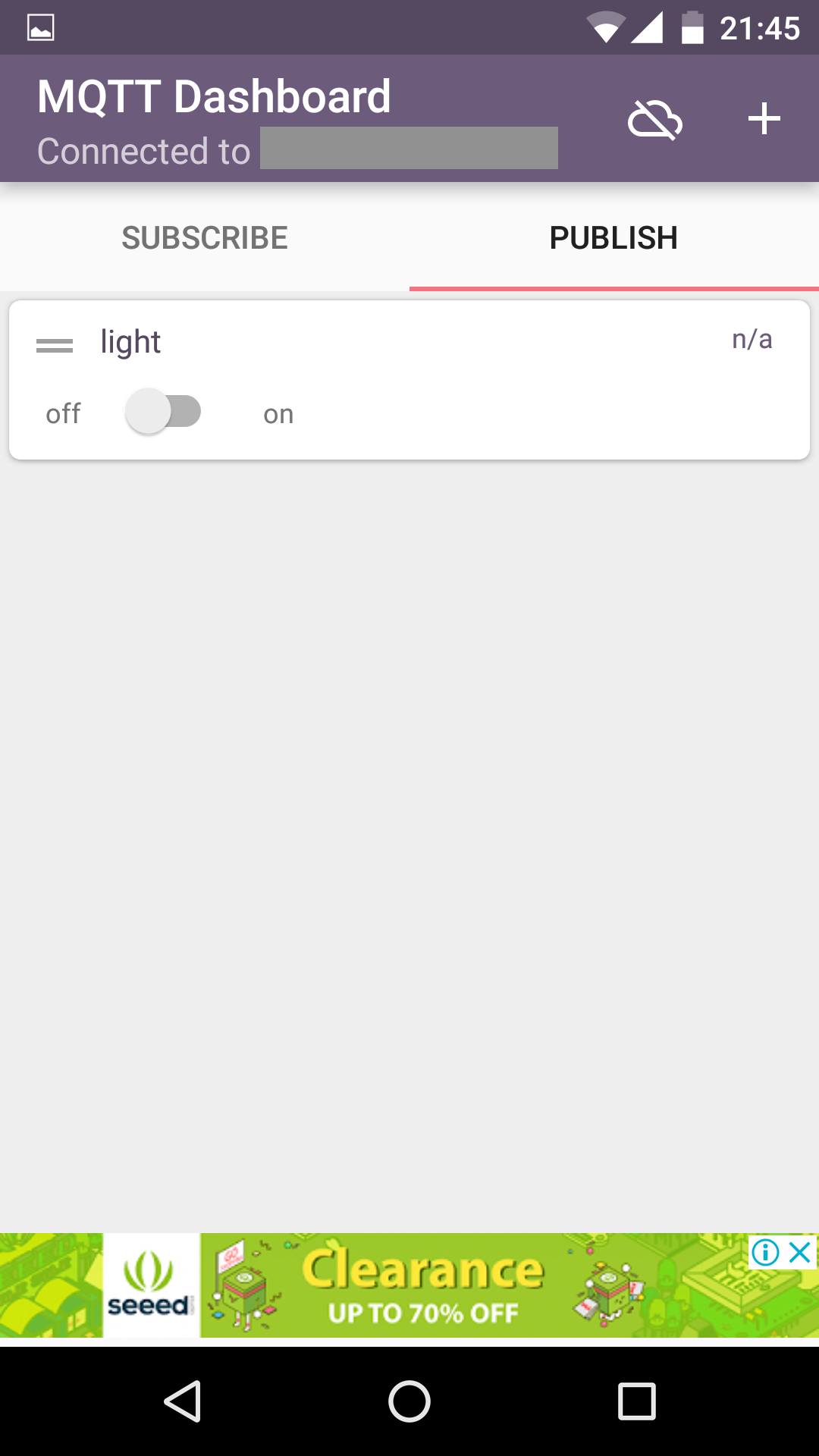
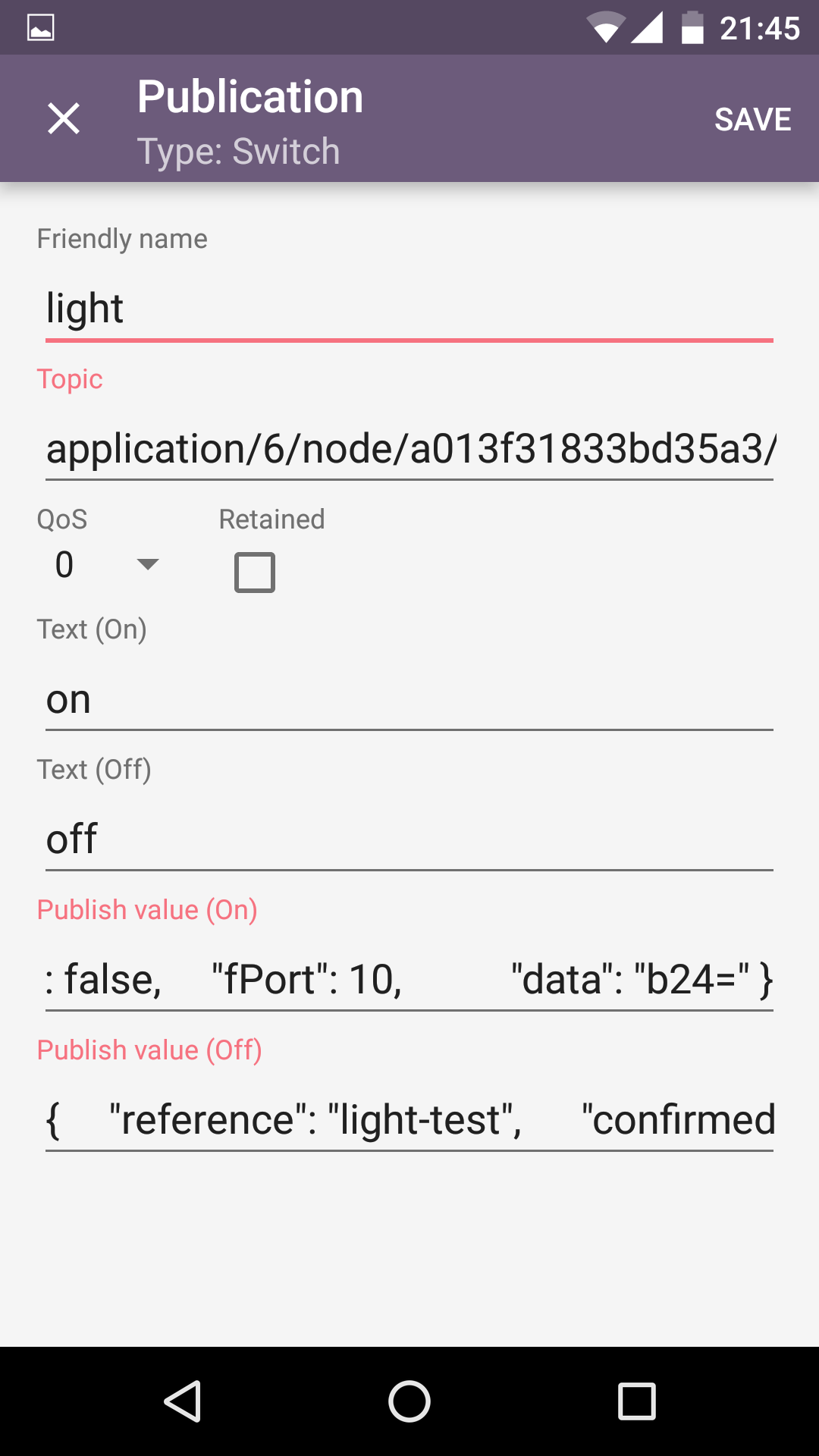
Start by configuring a connection (as in the figure on the left) and entering the IP address of the MQTT broker and the corresponding port (1883 by default). Click on the connection and then on the publish button. Now you can add different GUI components to public MQTT messages. In the center figure, we have selected a switch element. Long clicking on the switch takes you to the configuration. In this menu (figure on the right) you should enter the MQTT topic where you want to publish your message (as in application/APPLICATION_ID/node/DEVICE_EUI/tx) and the different messages for the on/off states (as explained in the previous section for mqtt-spy).
-. Receiving Downlink Messages
-. Autonomo with LoRaBee
In the LoRaWAN platform, we support devices based on an Autonomo board with a LoRaBee Microchip RN2483 module. According to http://shop.sodaq.com, Autonomo is a matchbox-sized powerhouse which uses the new Atmel Cortex M0+ 32bit micro controller. One advantage of such device is that it can be powered by a smartphone-sized solar panel. In order to configure the Autonomo with LoRaBee device, you can refer to Deploying an End-to-End LoRaWAN Platform.
This sketch example-code-autonomo.ino.zip can be used as an example. The following extract denotes the part corresponding to receiving downlink messages. for example, the received value can be used to trigger some action on the Arduino module.
case EV_TXCOMPLETE:
      Serial.println(F("EV_TXCOMPLETE (includes waiting for RX windows)"));
      if (LMIC.dataLen) {
        // data received in rx slot after tx
        Serial.print(F("Data Received: "));
        Serial.write(LMIC.frame + LMIC.dataBeg, LMIC.dataLen);
        Serial.println();
      }
-. Arduino with Dragino Shield
Devices in the LoRaWAN platform can also be implemented on Arduino boards with Dragino shields. The combined module as well as the basic configuration steps are presented in Simple Prototype of LoRa Communications. Similarly to the Autonomo device, you can download the following sketch example-code-arduino.ino.zip and modify it according to your preferences. Below you can find an extract of the receiving function for downlink messages.
void receiveData() {
  // After we have send some data, we can receive some data
  // First we make a buffer
  uint8_t payload[64];
  // Now we fill the buffer and
  // len = the size of the data
  uint16_t len = LoRaBee.receive(payload, 64);
  String HEXPayload = "";

  // When there is no payload the lorabee will return 131 (0x83)
  // I filter this out
  if (payload[0] != 131) {
    for (int i = 0; i < len; i++) {
      HEXPayload += char(payload[i]);
    }

    if (HEXPayload == "on") {
      digitalWrite(LED_BUILTIN, HIGH);
    }
    if (HEXPayload == "off") {
      digitalWrite(LED_BUILTIN, LOW);
    }
    debugSerial.println(HEXPayload);
    //switchLED(HEXPayload);
  } else {
    debugSerial.println("no payload");
  }
}
-. Selecting the Receive Windows
The selection of the receive window is one important parameter in receiving downlink messages. Here you should note these two important limitations:
- The LoraWAN-in-C library used on the Arduino based devices has only been tested for receiving downlink packets in the RX2 window.
- The Microchip LoRaBee is configured by default with RX2 corresponding to SF9 on the center frequency 869525000 Hz. However, the LoRaWAN specification recommends for RX2 the same sub-channel but with SF12.
Therefore, the recommended configuration consists of selecting to receive on RX2 for Arduino based devices (this is mandatory) and RX1 for autonomo based devices (this is the easiest configuration).
