This is an old revision of the document!
Table of Contents
ESIB IoT Challenge
Welcome to the ESIB IoT Challenge. In this challenge, you will be designing and prototyping the first IoT services based on a LoRaWAN network.
-. Platform
During this challenge, you will benefit from the first experimental platform implementing an end-to-end LoRaWAN solution in Lebanon. The platform consists of the following elements:
- Devices that communicate to one or more gateways via a wireless interface using single hop LoRa and implementing the LoRaWAN protocol. These devices are physically connected to sensors that generate data.
- Gateways or base stations that forward frames between the devices and the network server. Gateways are connected to the network server via IP interfaces.
- A LoRAWAN backend that implements the network server functions and provides frame control and security.
- Applications that enable to visualize and store the sensor data obtained from the devices.
- Where is the LoRa modulation implemented on the platform?
- What are the advantages of the LoRa modulation?
- How LoRa is compatible with LPWAN requirements and constraints?
- What is LoRaWAN? What is the difference between LoRaWAN and LoRa?
- Illustrate the protocol stacks on the LoRaWAN platform.
- What elements are IP enabled in the platform? What do you think about IP support in IoT?
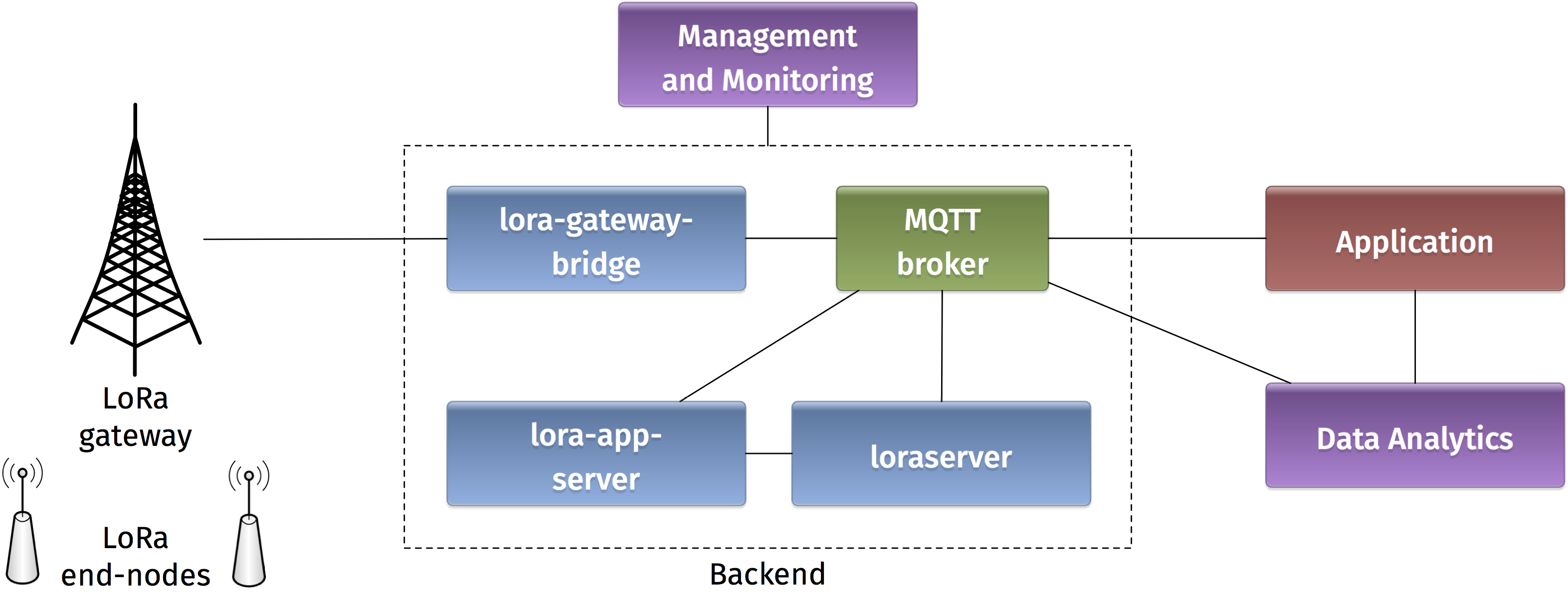
-. Backend
In a LoRaWAN network, the devices communicate with a Network Server through the gateway. The backend installed in the platform is based on an open-source LoRaWAN network-server https://www.loraserver.io. A web interface is available for configuring the applications and devices on the platform (https://212.98.XX.XX:8080).
Start by choosing the application named NTRE-1617 to create a new node. You should provide the following information:
- A unique node name:
NTRE-GX(whereXis your group number) - The node description
- A unique device EUI on 64 bits: Random identifiers can be generated on https://www.random.org/bytes/
- The application EUI on 64 bits:
0badde1cafe2deca. - A unique application key on 128 bits also obtained by random generation.
Make sure that the ABP activation button is unchecked, in order to enable OTAA join method. Finally, in advanced network settings, choose the receive window RX2.
- What does the application EUI mean? How is it used in LoRaWAN?
- What does the application key mean? How is it used in LoRaWAN security?
- Compare the two device activation methods used in LoRaWAN by giving the advantages and inconvenients.
- What is the difference between the two receive windows in LoRaWAN? What are they used for?
-. Devices
Devices in the LoRaWAN platform are implemented on Arduino boards with Dragino shields. The combined module as well as the basic configuration steps are presented in Simple Prototype of LoRa Communications.
Start by verifying the installation on your PC of the latest Arduino IDE. Drop the Arduino LMIC library in the corresponding folder. These tools are provided at the beginning of the challenge. Open the example sketch example-code-ntre-iot-challenge.ino with Arduino IDE.
- Give the characteristics of the Arduino you are using: model, number of pins, type of pins, memory sizes, etc.
- Give the main characteristics of the LoRa shield from Dragino (www.dragino.com).
- What type of Antenna are you using? Explain the corresponding characteristics.
Now you should configure your device with the same identifiers APPEUI, DEVEUI, and APPKEY as in the backend:
static const u1_t PROGMEM APPEUI[8]= { };
void os_getArtEui (u1_t* buf) { memcpy_P(buf, APPEUI, 8);}

// This should also be in little endian format, see above.
static const u1_t PROGMEM DEVEUI[8]= { };
void os_getDevEui (u1_t* buf) { memcpy_P(buf, DEVEUI, 8);}

static const u1_t PROGMEM APPKEY[16] = { };
void os_getDevKey (u1_t* buf) {  memcpy_P(buf, APPKEY, 16);}
Note that the device and application identifiers should be in little endian format, while the application key is in big endian format. For example, 0badde1cafe2deca is written as 0xCA, 0xDE, 0xE2, 0xAF, 0x1C, 0xDE, 0xAD, 0x0B in the Arduino sketch.
Let us analyze to radio parameters in the sketch by answering the following questions.
- In the setup function, which channels are activated on the device?
- What are the different spreading factors on each channel?
- What is the regulation on the radio channels in LoRa?
The LMIC library defines a set of events corresponding to the protocol machine state. These events appear in the onEvent() function.
- What is the difference between the JOINING and the JOINED events?
- When is the EV_TXCOMPLETE event called?
Finally let us look at the message sending on the device.
- What is the function for sending messages on the device? How it is called?
- What is the period of message sending? Explain the implementation choice.
- Is this period guaranteed according to the LoRaWAN specification?
Now you are ready to compile the sketch and upload it to the LoRaWAN device. Connect the device a USB port on your PC, choose the board type as Arduino/Genuino Mega 2560 and select the corresponding port. Compile and upload!
For Arduino Mega 2560, additional drivers can be installed on Windows from http://wch.cn/download/CH341SER_ZIP.html.
Open the serial monitor in the Arduino IDE at 115200 baud and analyse the debug messages.
- What is the radio transmit parameters of the captured debug messages?
- What is the radio receive parameters of the captured debug messages for the two receive windows?
Getting back to the backend, you can monitor some important information related to your device. Click on the corresponding node session.
- What are the different fields that appear in the node session corresponding to you device?
- Explain how each field is created according to the LoRaWAN specification.
- What are the different counters visible at the backend? Explain how they get incremented and how they are used.
-. Applications
mqtt-spy is an open source utility intended to help you with monitoring activity on MQTT topics. It has been designed to deal with high volumes of messages, as well as occasional publications. mqtt-spy is a JavaFX application, so it should work on any operating system with an appropriate version of Java 8 installed. A very useful tutorial is available on https://github.com/eclipse/paho.mqtt-spy/wiki.
You can use mqtt-spy to debug the messages received from the LoRaWAN devices. The tool is provided at the beginning of the challenge. After starting the application, configure a new connection to the MQTT broker by simply adding the IP address of the broker in the Server URI field. Now you can subscribe to any MQTT topic. If you want to receive all messages arriving at the backend, you can use the generic topic #. You can also limit to the topic including the messages of any specific device: application/APPLICATION_ID/node/DEVICE_EUI/rx.
- Summarize the concepts and functionalities of the MQTT protocol.
- What are the possible strengths and weaknesses in terms of security of MQTT?
- What are the different types of topics used by the backend? Explain.
- Explain the different fields in a captured MQTT message received from you device.
The payload received by the MQTT client is decrypted but encoded in Base64. You should decode it to get the original message.
If you need to send data to your device, you should publish the encoded message in the corresponding topic application/APPLICATION_ID/node/DEVICE_EUI/tx as follows:
{
    "reference": "abcd1234",                  // reference which will be used on ack or error (this can be a random string)
    "confirmed": false,                        // whether the payload must be sent as confirmed data down or not
    "fPort": 10,                              // FPort to use (must be > 0)
    "data": "...."                            // base64 encoded data (plaintext, will be encrypted by LoRa Server)
}
-. Day One Challenges
-. The End-to-End Challenge
I can send data from the device to the application.
-. The Downlink Challenge
I can send data from the application to the device.
-. The Radio Challenge
I can tune the LoRa radio parameters and assess the results.
These two commands can be helpful when used after the join event:
LMIC_disableChannel(N);
LMIC_setDrTxpow(DR_SF12,14);
-. The Sensor Challenge
I can use different sensors to send data from the device: PIR, moisture, temperature, light, etc.
-. Day Two Challenges
-. The Wind Rises
This is a mandatory challenge. It consists of using Node-RED to receive data from the sensors (via MQTT) and send it to emoncms for visualization.
| Provided material |
|---|
| VM with Node-RED installed |
| Node-RED example flow |
| Dashboard example |
| Required skills |
|---|
| Basic javascript |
| GUI configuration |
| Two drops of IoT design |
-. Nausicaa Challenge
You have to take control on the devices. Use some scripting to send commands or tune some parameters on the devices.
| Required skills | |
|---|---|
| Basic scripting (for example python) | |
| Basic electronics | |
| Two drops of IoT autocracy |
-. Totoro Challenge
You have to store the sensor data in a database. Use Node-RED to inject data in a (influx) database.
| Required skills |
|---|
| Basic database |
| Two drops of IoT resilience |
-. Kiki Challenge
You have to implement a radio coverage test on the campus.
| Required skills |
|---|
| Basic scripting |
| Two drops of IoT ubiquity |
-. Mononoke Challenge
You have to implement a chat bot designed for working with Google Hangouts. The bot answers requests and reveals sensors data.
| Required skills |
|---|
| Basic scripting with python |
| Two drops of IoT robot attitude |