This is an old revision of the document!
Table of Contents
Deploying an End-to-End LoRaWAN Platform
Starting from September 2016, Saint-Joseph University of Beirut (USJ) will be deploying the first academic LoRa network in Lebanon. The network will support monitoring of micro-climate conditions in vineyards. Here below you can find a detailed description of the experimental platform implementing an end-to-end LoRaWAN solution. The platform consists of the following elements:
- Wireless devices with a sensing interface and a communication interface implementing the LoRaWAN protocol.
- Gateways or base stations that relay the radio frames to the IP backend.
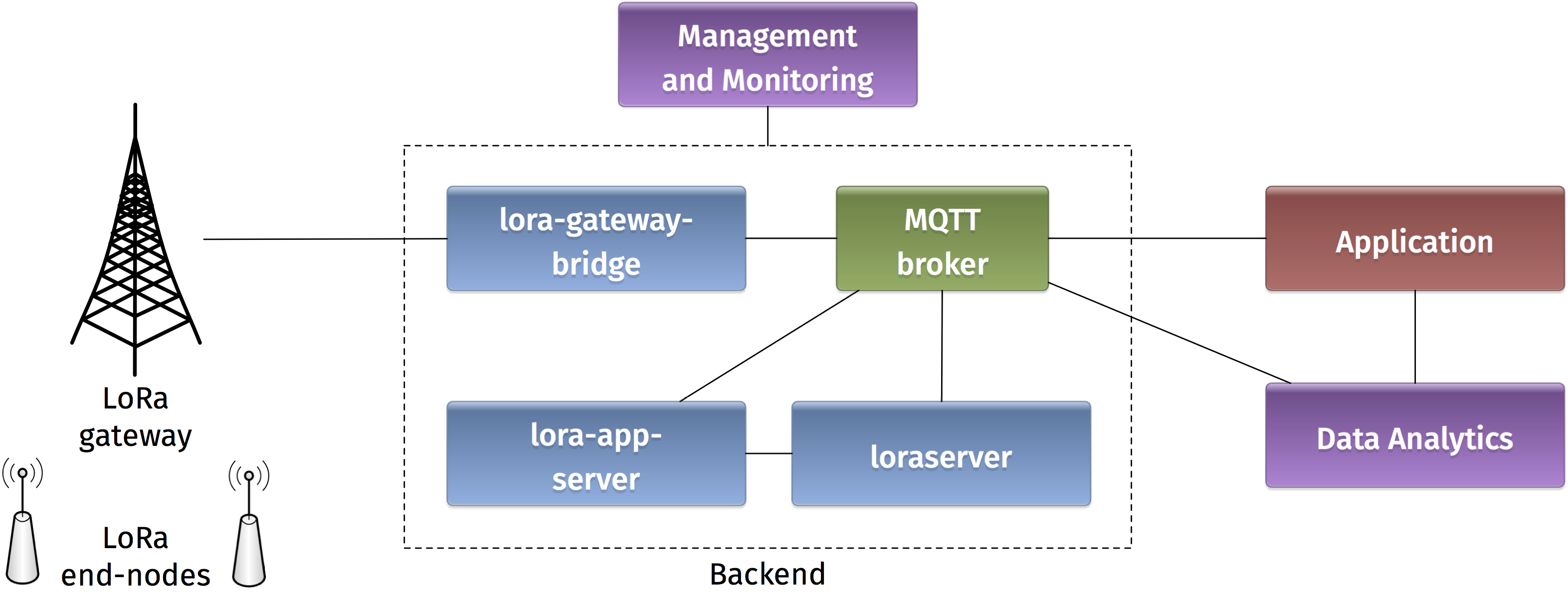
- A LoRAWAN backend implementing the network server function.
- Application examples that enable to visualize and store the sensor data.
-. Devices
-. Autonomo with LoRaBee
Starting with the devices in the LoRaWAN platform, we will use an Autonomo board with a LoRaBee Microchip RN2483 module. According to http://shop.sodaq.com, Autonomo is a matchbox-sized powerhouse which uses the new Atmel Cortex M0+ 32bit micro controller. One advantage of such device is that it can be powered by a smartphone-sized solar panel.
In order to configure the Autonomo with LoRaBee device, you should follow these steps:
- Verify that you have the latest Arduino IDE from https://www.arduino.cc/en/Main/Software on your computer.
- Install the board files as noted in http://support.sodaq.com/sodaq-one/autonomо/getting-started-autonomo/.
- Add the following library sodaq_rn2483_2.zip to your Arduino IDE as explained in https://www.arduino.cc/en/guide/libraries.
Now you are ready to write a sketch for the device. Here is one example sketch test-lorawan-combined-loraserver-example.zip where the autonomo is connected to three sensors: light, moisture, and temperature. Let us analyse some extracts of the code.
In this part, you should put the keys for Over-The-Air Activation (OTAA) as explained in the LoRaWAN specification:
// USE YOUR OWN KEYS!
const uint8_t devEUI[8] =
{ };

// USE YOUR OWN KEYS!
const uint8_t appEUI[8] =
{ };

const uint8_t appKey[16] =
{ };
The pins for connecting the sensors are specified in these declarations (A0 for light sensor, A2 for moisture sensor, and D0 temperature sensor):
int light_pin = A0;
int moisture_pin = A2;
int temperature_pin = 0;
int temperature_vcc_pin = 1;
int moisture_vcc_pin = 8;
int moisture_gnd_pin = 7;
The OTAA method is used for joining the network and Adaptive Data Rate (ADR) is activated:
LoRaBee.initOTA(loraSerial, devEUI, appEUI, appKey, true)
Eight different sub channels are activated with data rate ranges from 0 to 5:
LoRaBee.configChFreq(0, 868100000L,0,5,1);
LoRaBee.configChFreq(1, 868300000L,0,5,1);
LoRaBee.configChFreq(2, 868500000L,0,5,1);
LoRaBee.configChFreq(3, 867100000L,0,5,1);
LoRaBee.configChFreq(4, 867300000L,0,5,1);
LoRaBee.configChFreq(5, 867500000L,0,5,1);
LoRaBee.configChFreq(6, 867700000L,0,5,1);
LoRaBee.configChFreq(7, 867900000L,0,5,1);
Finally, the message containing the sensor values is sent in an unconfirmed uplink message:
LoRaBee.send(1, (uint8_t*)message.c_str(), message.length())
-. Arduino with Dragino Shield
Devices in the LoRaWAN platform can also be implemented on Arduino boards with Dragino shields. The combined module as well as the basic configuration steps are presented in Simple Prototype of LoRa Communications. As for the Autonomo device, you can download the following sketch test-loraserver-comb-loraserver-dragino.zip and modify it according to your preferences. Below you can find somme commented extracts of the sketch.
The pin mapping corresponds to the Dragino electronic schematic:
const lmic_pinmap lmic_pins = {
    .nss = 10,
    .rxtx = LMIC_UNUSED_PIN,
    .rst = 9,
    .dio = {2, 6, 7},
};
The send function is rescheduled TX_INTERVAL seconds after each transmission complete event:
        case EV_TXCOMPLETE:
            Serial.println(F("EV_TXCOMPLETE (includes waiting for RX windows)"));
            if(LMIC.dataLen) {
                // data received in rx slot after tx
                Serial.print(F("Data Received: "));
                Serial.write(LMIC.frame+LMIC.dataBeg, LMIC.dataLen);
                Serial.println();
            }
            // Schedule next transmission
            os_setTimedCallback(&sendjob, os_getTime()+sec2osticks(TX_INTERVAL), do_send);
            break;
This send function is initially scheduled here:
do_send(&sendjob);
The message containing the sensor values is transmitted on one of the radio channels (as in the Autonomo case):
LMIC_setTxData2(1, (uint8_t*) buffer, message.length() , 0);
The adaptive data rate is not supported, and the spreading factor is configured as follows:
LMIC_setDrTxpow(DR_SF7,14);
-. Gateways
-. Single Channel Gateway
The single channel gateway includes a LoRa transmission module (Dragino Shield) connected to a Raspberry Pi (2 or 3) as shown in Figure 1. Communication between the two modules is done over an SPI interface.
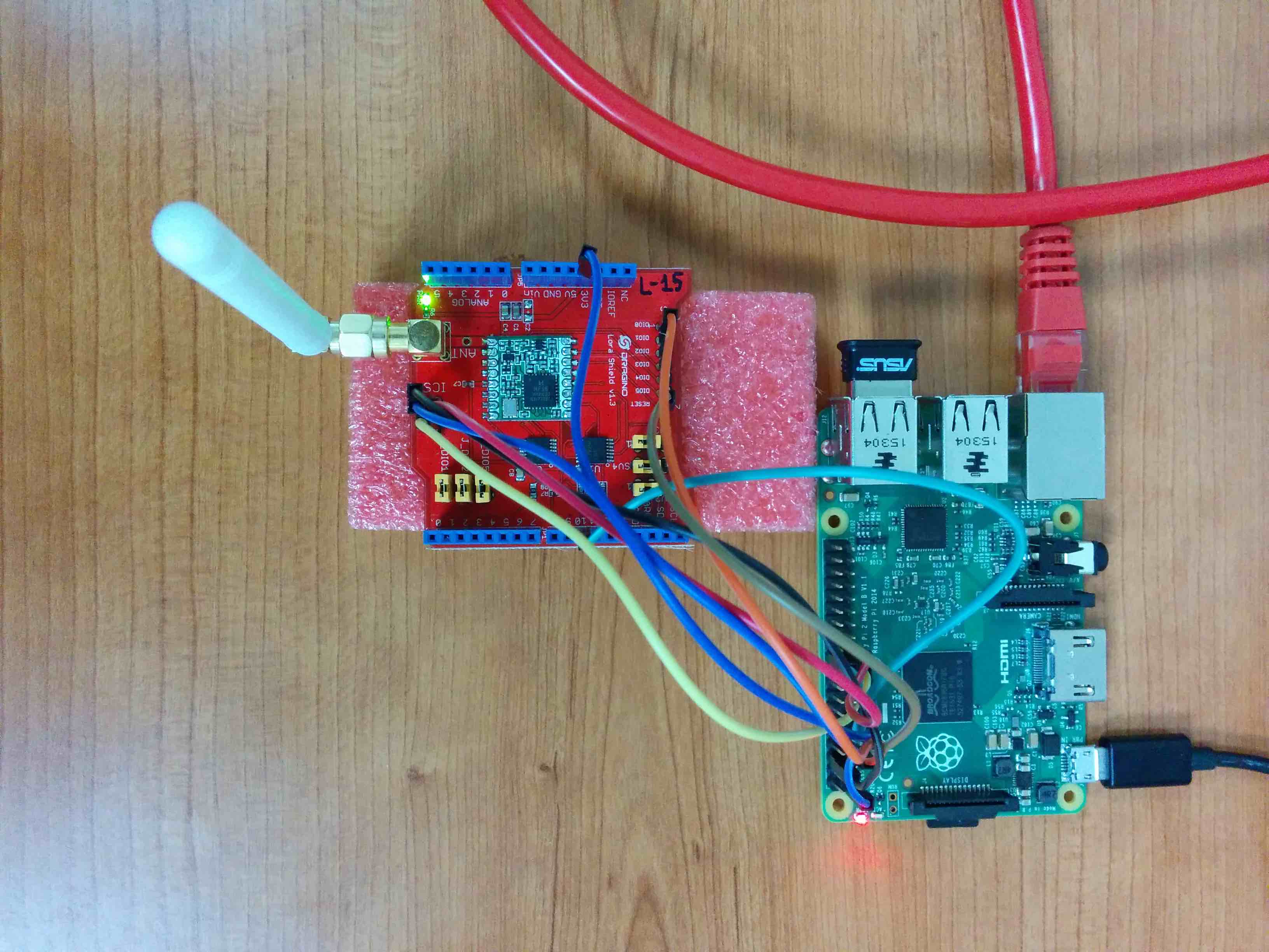
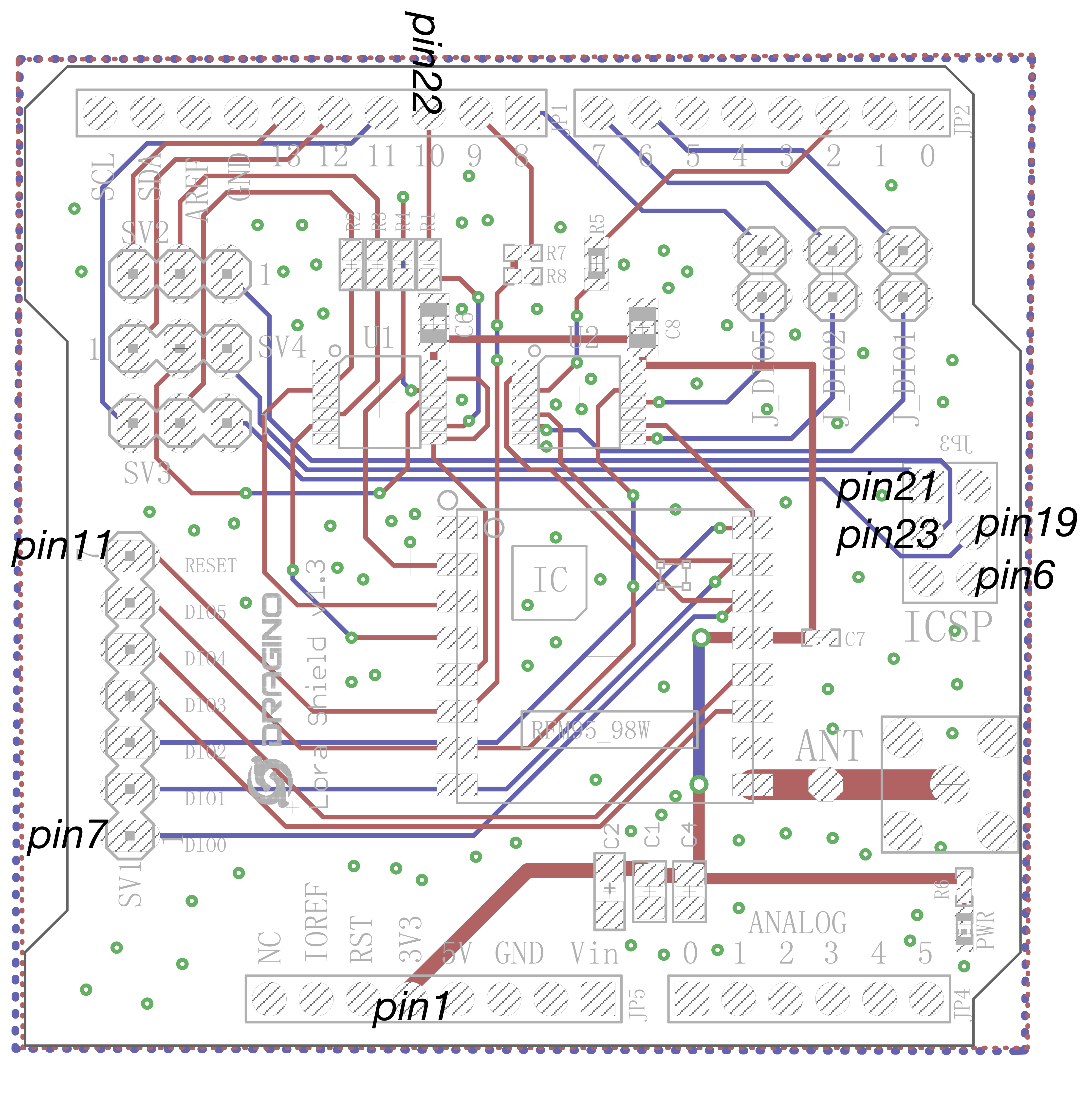
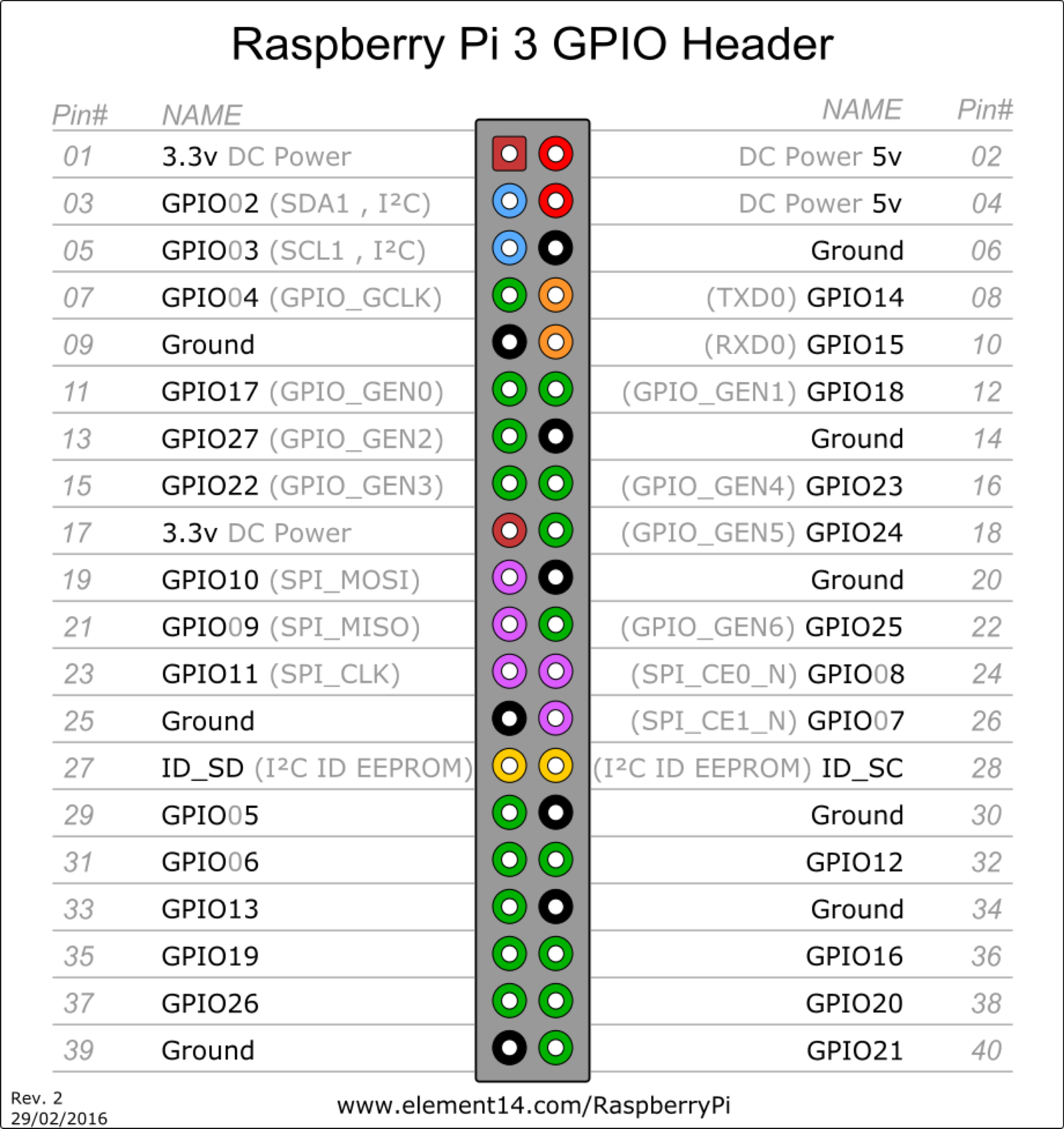
In order to assemble the gateway, start by making the wire connections: the connection pins are identified in Figures 2 and 3.
Connect the Raspberry Pi to the Internet and install the packet forwarding software. The source code of the single channel packet forwarder is available on: https://github.com/samerlahoud/single_chan_pkt_fwd. In order to install it, you need to:
- Enable SPI on the Raspberry Pi using raspi-config
- Download and unzip the source code:
wget https://github.com/hallard/single_chan_pkt_fwd/archive/master.zip
unzip master.zip
- Install the wiring library:
apt-get update
apt-get install wiring
Compile the packet forwarder:
make all
For gcc version 4.6.3, a compilation error results in the following warning unrecognized command line option '-std=c++11'. Replace -std=c++11 by -std=c++0x in the Makefile and recompile:
CFLAGS = -std=c++0x -c -Wall -I include/
Now, you need to configure the single channel packet forwarder. This is done in the global_conf.json configuration file. Particularly, you need to choose the channel, the spreading factor, the pins for SPI communication, and the address of the backend server. Note that you can specify multiple backends for testing purposes.
- global_config.json
{
  "SX127x_conf":
  {
    "freq": 868100000,
    "spread_factor": 7,
    "pin_nss": 6,
    "pin_dio0": 7,
    "pin_rst": 0,
    "pin_led1":4
  },
  "gateway_conf":
  {
    "ref_latitude": 33.86576536772,
    "ref_longitude": 35.56378662935,
    "ref_altitude": 165,

    "name": "ESIB SC Gateway",
    "email": "cimti@usj.edu.lb",
    "desc": "Dragino Single Channel Gateway on RPI",

    "servers":
    [
      {
        "address": "router.eu.thethings.network",
        "port": 1700,
        "enabled": true
      },
      {
        "address": "212.98.137.194",
        "port": 1700,
        "enabled": true
      },
      {
        "address": "172.17.17.129",
        "port": 1700,
        "enabled": false
      }
    ]
  }
}
Finally, you can run the packet forwarder as root!
nohup ./single_chan_pkt_fwd &
-. Kerlink IoT Station
# activates eth0 at startup
ETHERNET=yes
# claims dhcp request on eth0
ETHDHCP=yes

# Selector operator APN
GPRSAPN=gprs.touch.com.lb
# Enter pin code if activated
GPRSPIN=0000
# Update /etc/resolv.conf to get dns facilities
GPRSDNS=yes
# PAP authentication
GPRSUSER=
GPRSPASSWORD=

# Bearers priority order
#BEARERS_PRIORITY="eth0,ppp0,eth1"
BEARERS_PRIORITY="ppp0,eth0,eth1"
./gps-pkt-fwd.sh > /dev/null &
 3270 root      2548 S    /bin/sh ./gps-pkt-fwd.sh
 3288 root     34908 S    ./gps_pkt_fwd
/etc/init.d/gprs start

[root@Wirgrid_0b03008c demo_gps_loramote]# /etc/init.d/gprs  status
pppd (pid 5273) is running...
Session: Rx=58, Tx=163
Globals: Rx=1130457, Tx=1195592
Sum:     Rx=1130515, Tx=1195755
[root@Wirgrid_0b03008c demo_gps_loramote]#