Table of Contents
Simple Prototype of LoRa Communications
As defined by Semtech, LoRa is a wireless technology developed to create the low-power, wide-area networks (LPWANs) required for machine-to-machine (M2M) and Internet of Things (IoT) applications. The technology offers a very compelling mix of long range, low power consumption and secure data transmission and is gaining significant traction in IoT networks being deployed by wireless network operators.
In the following, we present a prototype of LoRa communication between two wireless modules. This enables to get basic insights on the implementation of the technology and prepares some advanced prototypes and experimentations.
1. Hardware and Cost
2. Software
- RadioHead: The Packet Radio library for embedded microprocessors can be downloaded from http://www.airspayce.com/mikem/arduino/RadioHead/ or from this direct link.
- Arduino IDE: Specific OS versions can be downloaded from https://www.arduino.cc/en/Main/Software.
3. Compatibility
This tutorial is written for :
- Arduino IDE 1.6.9.
- RadioHead 1.61.
- Dragino hardware release v1.3.
- Mac OS 10.11.5.
Beware of the necessary modifications, if any of the previous specifications is not supported in your case.
4. Installation
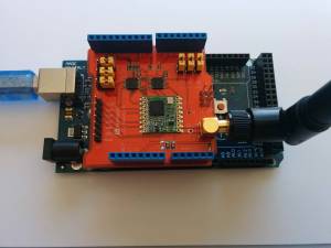
Start by plugging the Dragino shields on the Arduino devices and mounting the antennas as shown in Fig. 1.
Connect the two Arduino devices to USB ports on your computer. If this is the first time you use Arduino IDE, make sure to install the necessary USB drivers by selecting Tools > Boards Manager and installing Arduino AVR boards.
Now, you have to select the corresponding Board and Port in the Tools menu to program your Arduino. For example, you can use the following:
- For Arduino Uno: Board = Arduino/Genuino Uno Mega, Port = /dev/cu.wchusbserial1420.
- For Arduino Mega: Board = Arduino/Genuino Mega 2560, Port = /dev/cu.usbmodem141511.
Unzip the RadioHead library and copy it to your sketchbook library folder as detailed in https://www.arduino.cc/en/Guide/Libraries.
For Arduino Mega 2560, additional drivers can be installed from http://wch.cn/download/CH341SER_ZIP.html.
5. Running Basic Sketches
Start by setting the central frequency of the LoRa modules. For this, open the RH_RF95.cpp file locate in the RadioHead folder and change the frequency to 868.1 Mhz:
- RH_RF95.cpp
setFrequency(868.1);
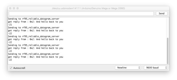
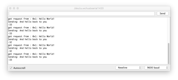
Download the basic sketches that implement a reliable LoRa communication between the two modules. Open the sketches with Arduino IDE, compile and upload on the two arduino modules, respectively. On the serial interfaces, you should obtain similar results as in Fig. 2 and Fig. 3. The client sends a Hello World! message and waits for an acknowledgement message from the server. Both modules output the RSSI (received power in dBm) for each received message.
6. Modifying the Radio Parameters
The typical configuration for LoRa modules consists of 125 KHz sub-channels, a coding rate of 4/5, and a spreading factor equal to 7. This configuration ensures higher data rates but is more vulnerable in case of harsh radio conditions. If you want to ensure more robustness to noise on the radio channel or extend the coverage, you may change the module configuration to a stronger coding rate of 4/8 and a spreading factor of 12. This obviously comes at the expense of lower data rates! The procedure is explained in the following.
Start by modifying the modem config in RH_RF95.cpp:
- RH_RF95.cpp
//setModemConfig(Bw125Cr45Sf128); // Radio default
setModemConfig(Bw125Cr48Sf4096); // slow and reliable?
As the data rate is lower, you may need to increase the timeout before declaring a lost transmission. For this, you add a variable in RH_LONG_TIMEOUT.h that equals 8 seconds and set the equivalent timeout in RHReliableDatagram.cpp as shown hereafter.
- RHReliableDatagram.h
#define RH_LONG_TIMEOUT 8000
- RHReliableDatagram.cpp
RHReliableDatagram::RHReliableDatagram(RHGenericDriver& driver, uint8_t thisAddress)
    : RHDatagram(driver, thisAddress)
{
    _retransmissions = 0;
    _lastSequenceNumber = 0;
    //_timeout = RH_DEFAULT_TIMEOUT;
    _timeout = RH_LONG_TIMEOUT;
    _retries = RH_DEFAULT_RETRIES;
}
RHReliableDatagram class introduces acknowledgement messages. It may be preferable to use the basic class RH_RF95 in this simple prototype.


